(Click on pictures to enlarge)
Also see my personal (non-ham) home page at www.cbjohn.com
|
|
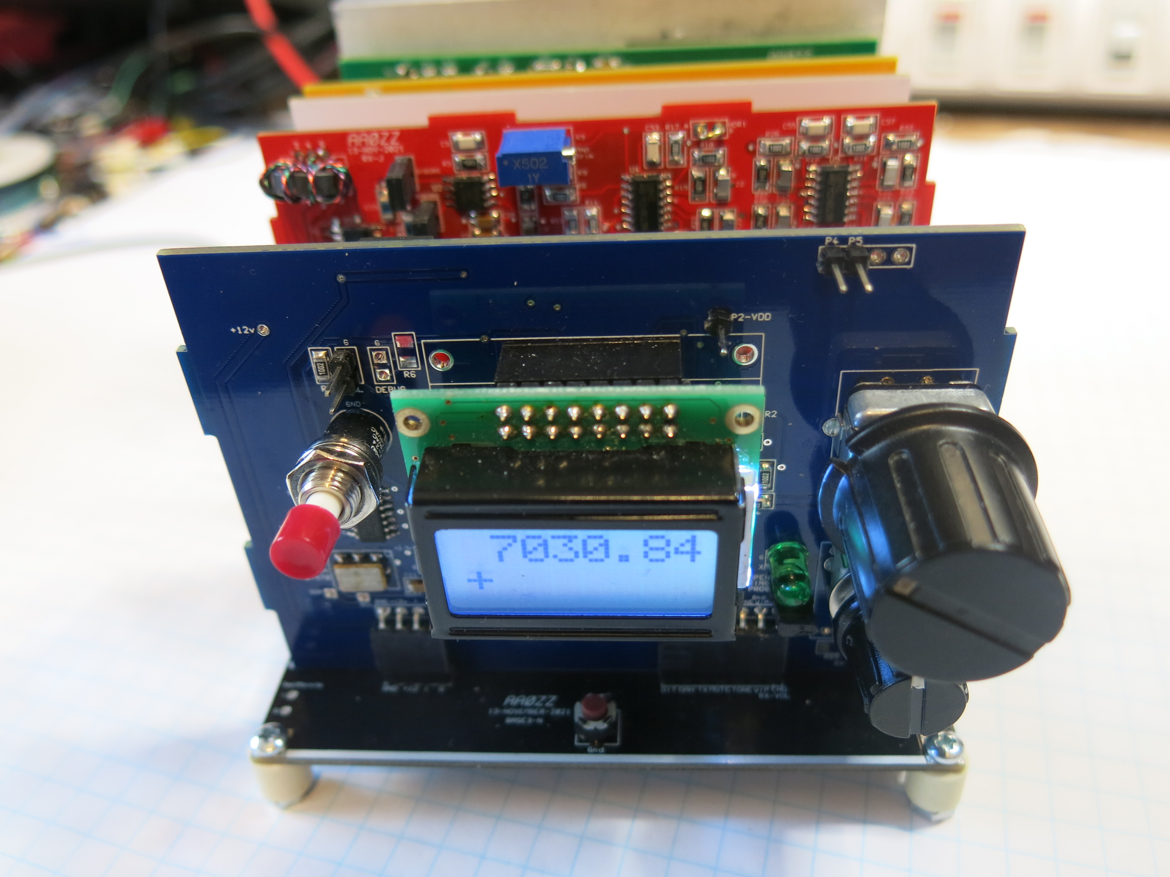
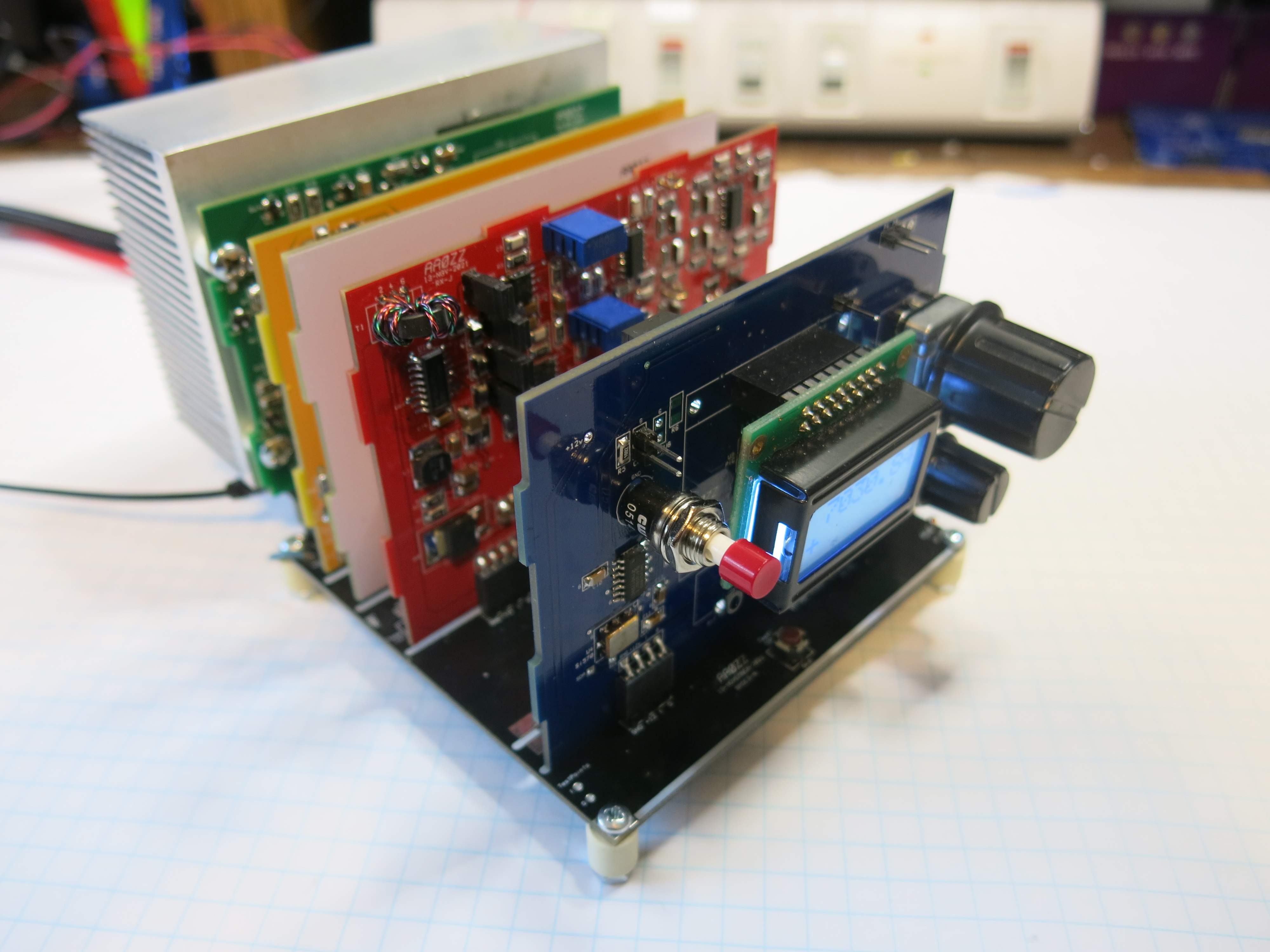
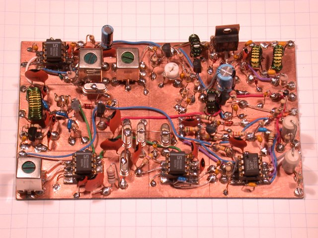
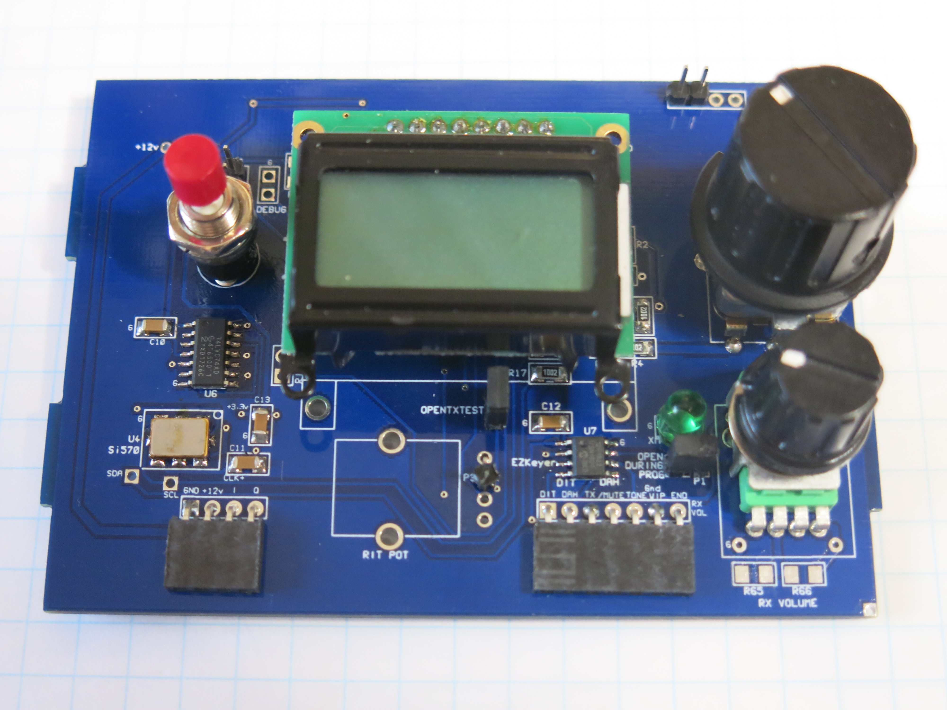
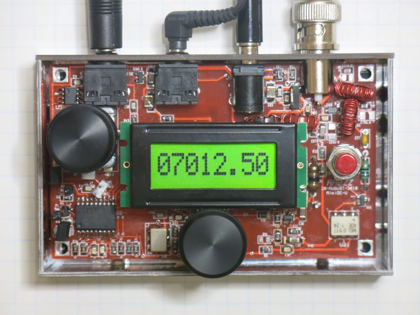
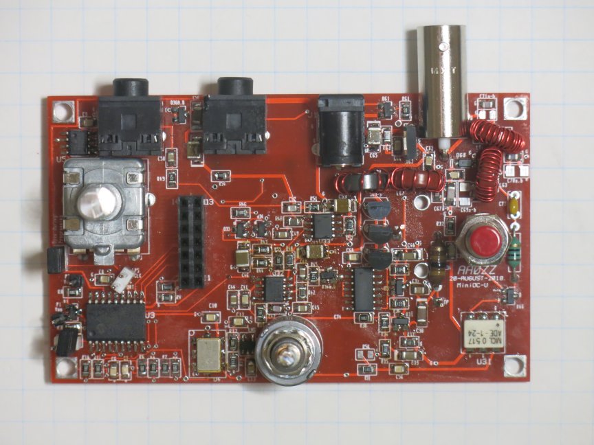
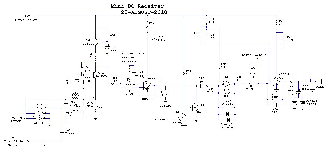
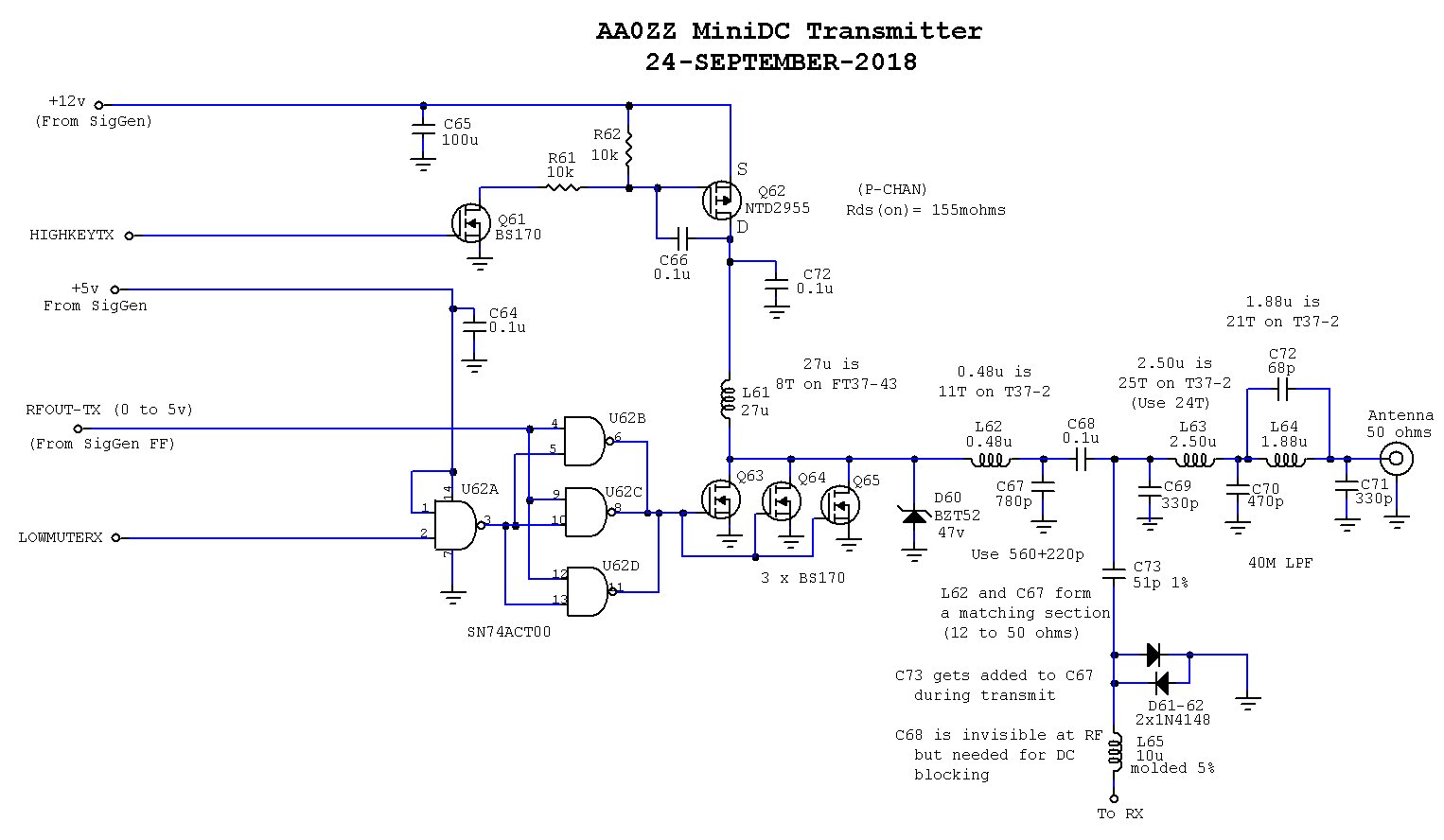
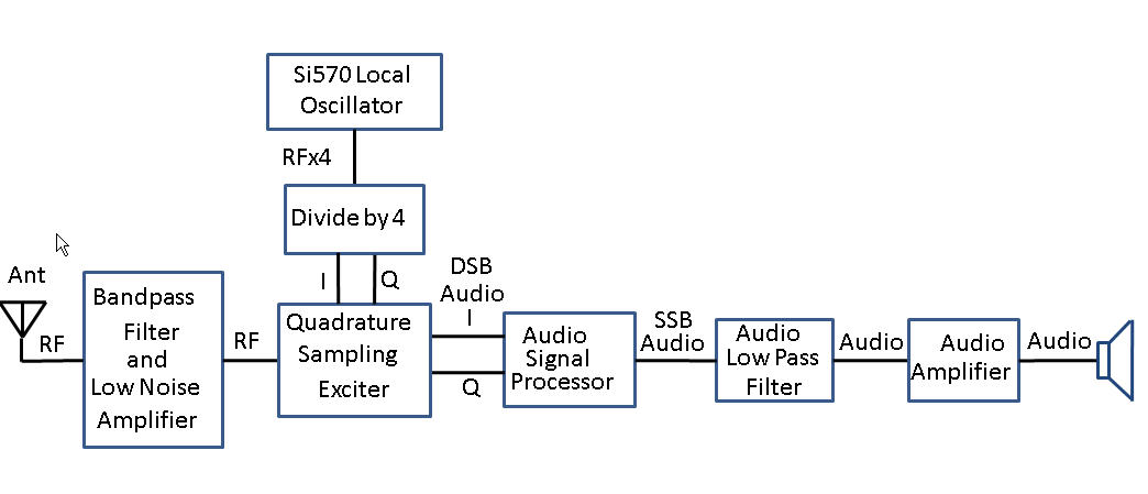
40M Direct Conversion Transceiver Dimensions: 4" x 2.5" 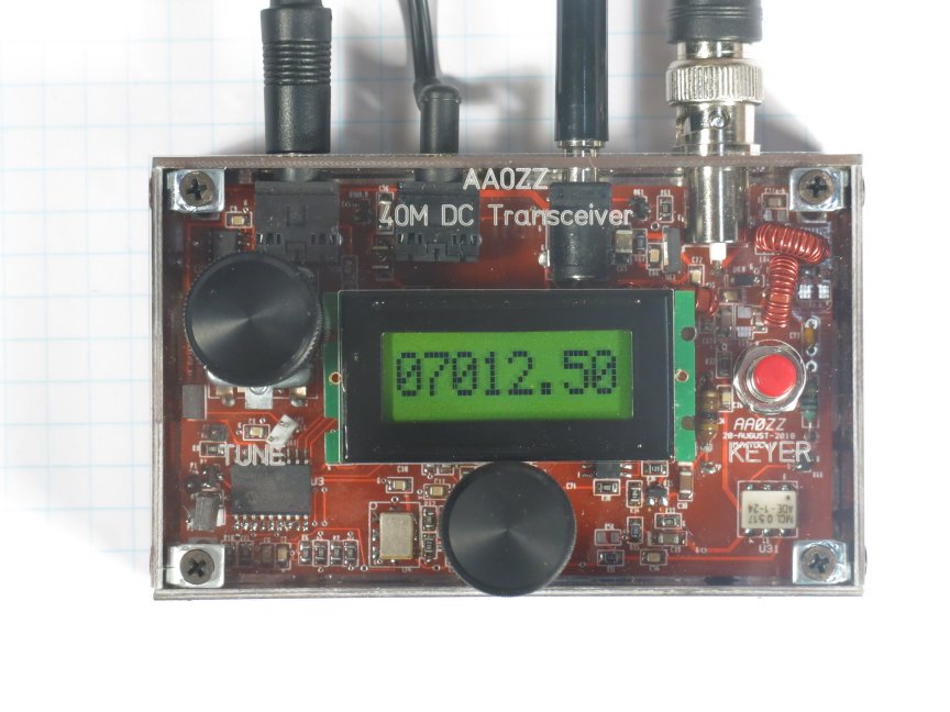
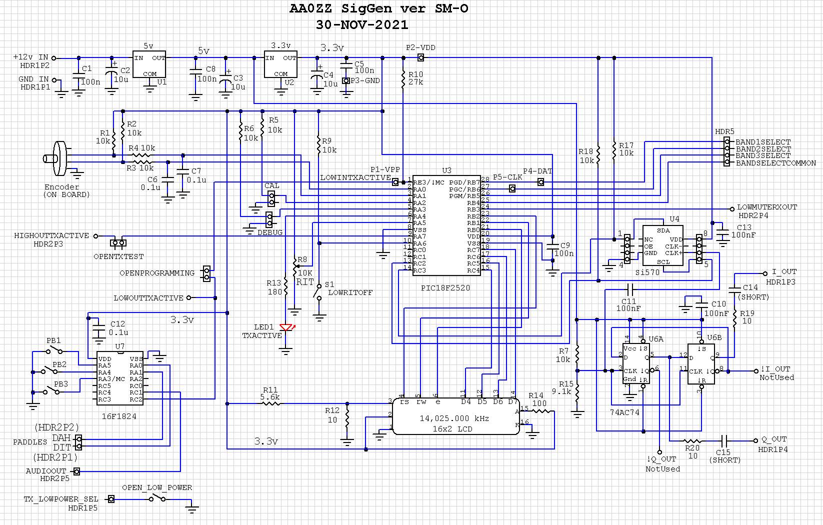
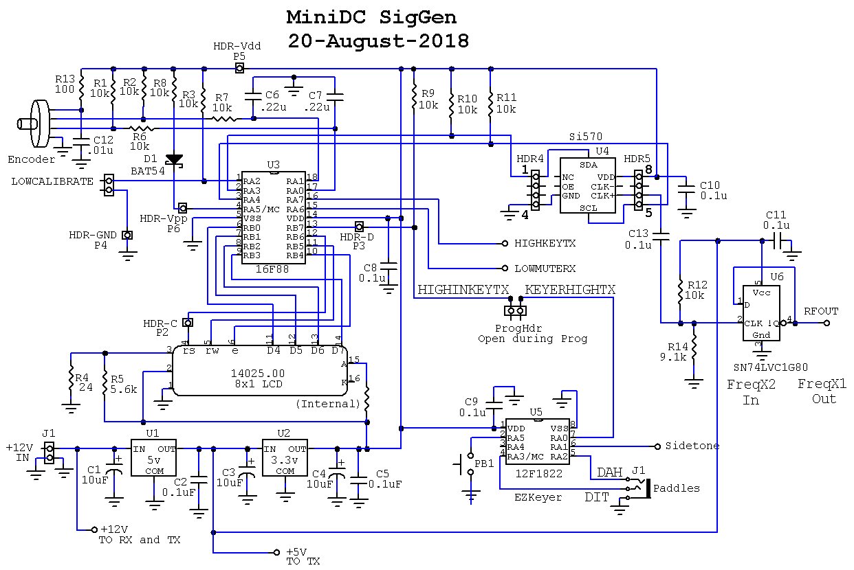
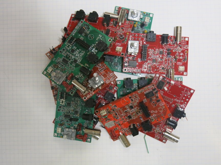
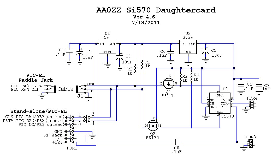
MiniDC with no case, LCD, knobs (JPG) Signal Generator Schematic (JPG) "Boneyard" of forgotten MiniDC favorites(JPG)
|
|
Dimensions: 4" wide, 2.5" deep, 0.75" high (BLACK) 4.5" wide, 4" deep, 1.5" high (BLUE) 5.5" wide, 5" deep, 2" high (RED) 6.5" wide, 6" deep, 2" high (PURPLE) Enclosure Assembly Manual (PDF) |
|
|
My QST Article - July 2016

(Click to enlarge)
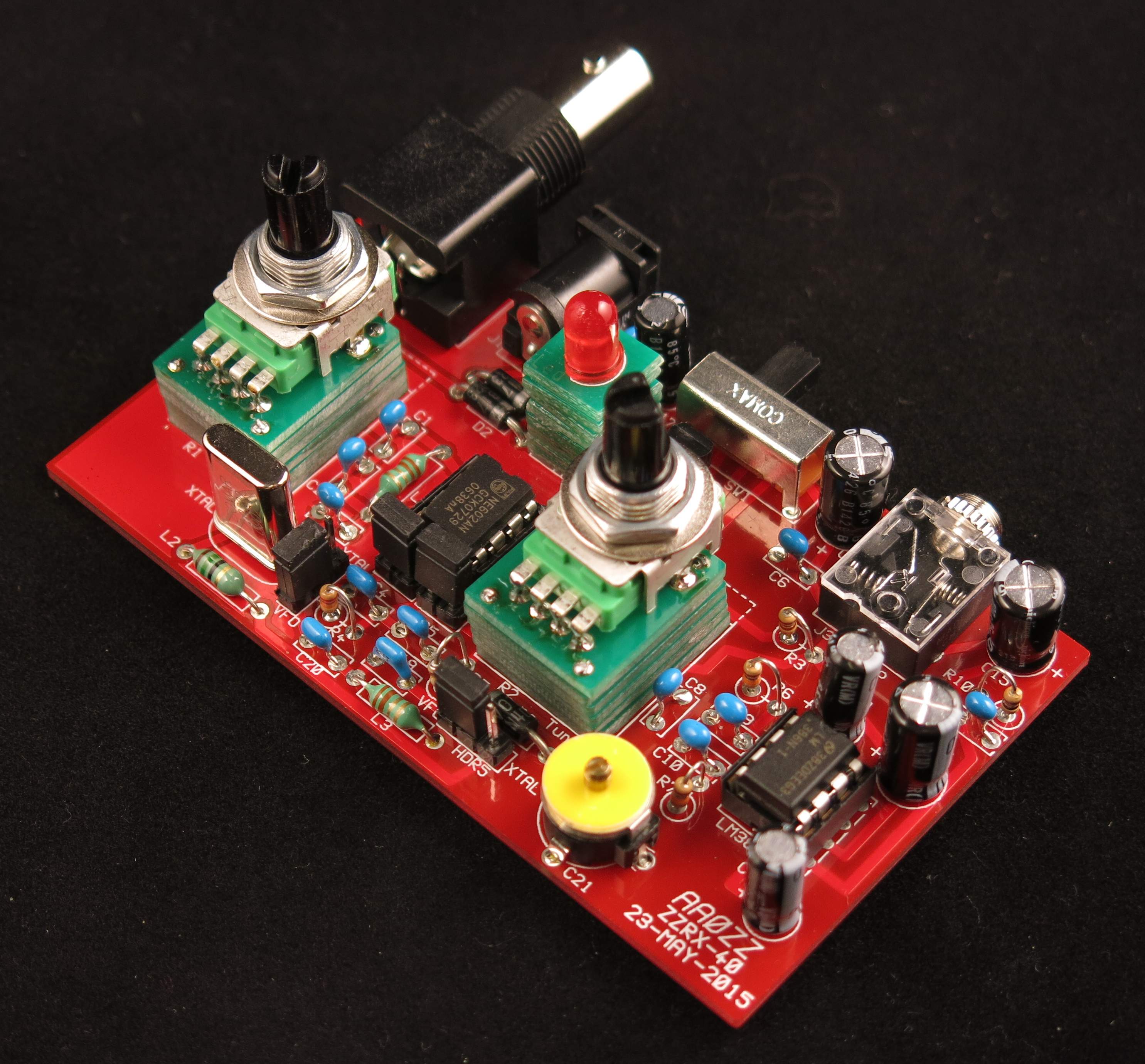
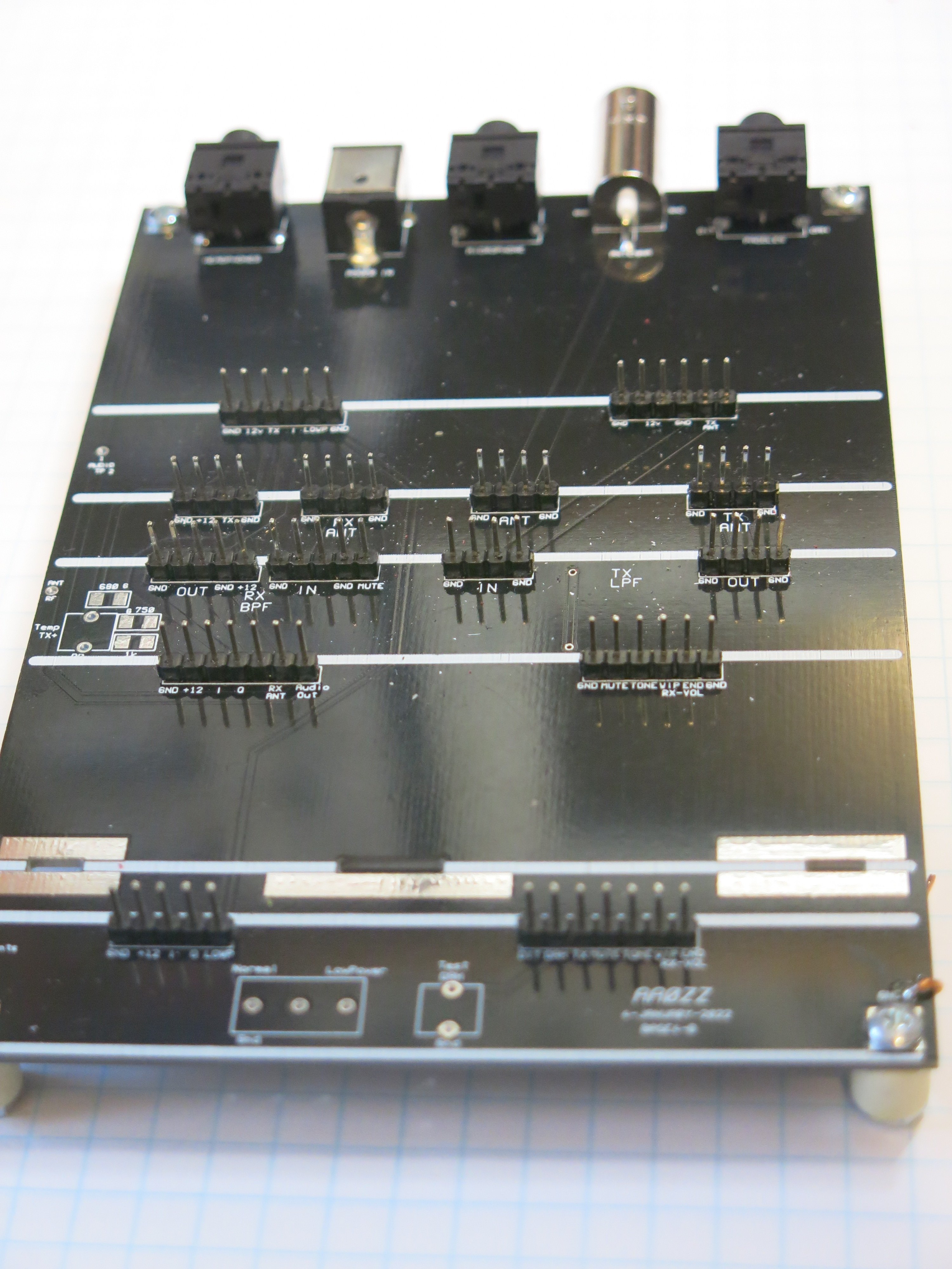
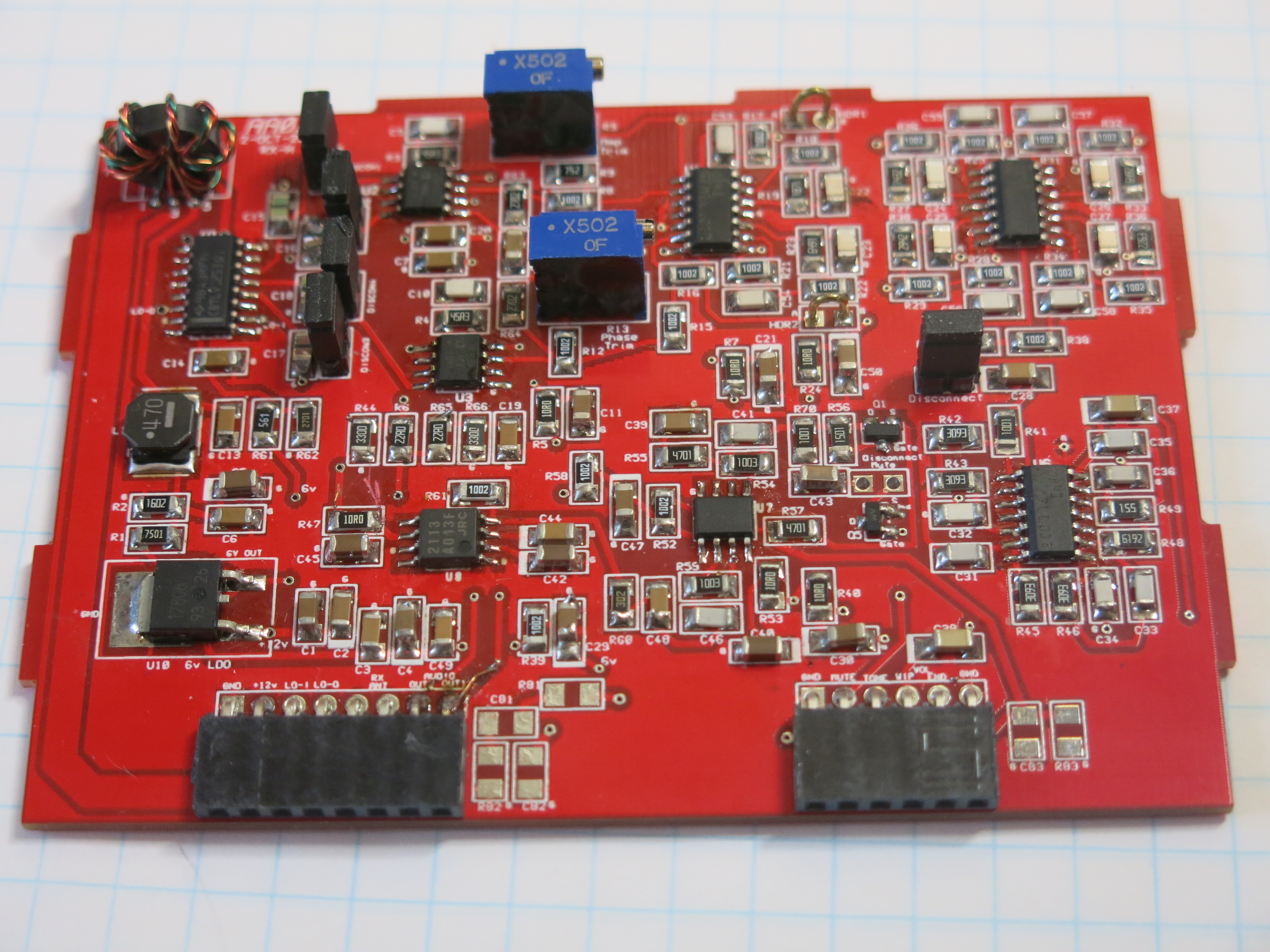
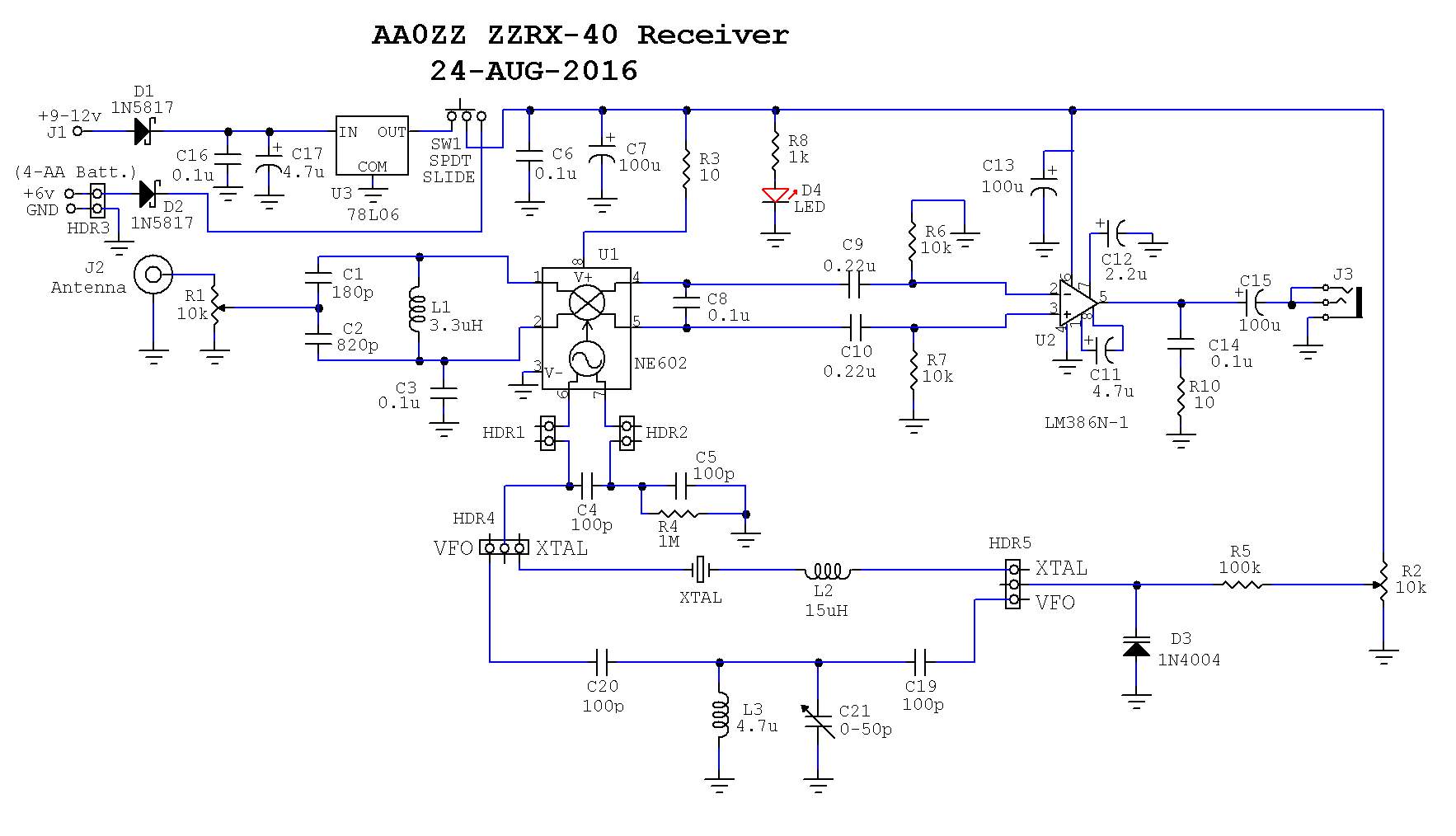
ZZRX-40 PCB
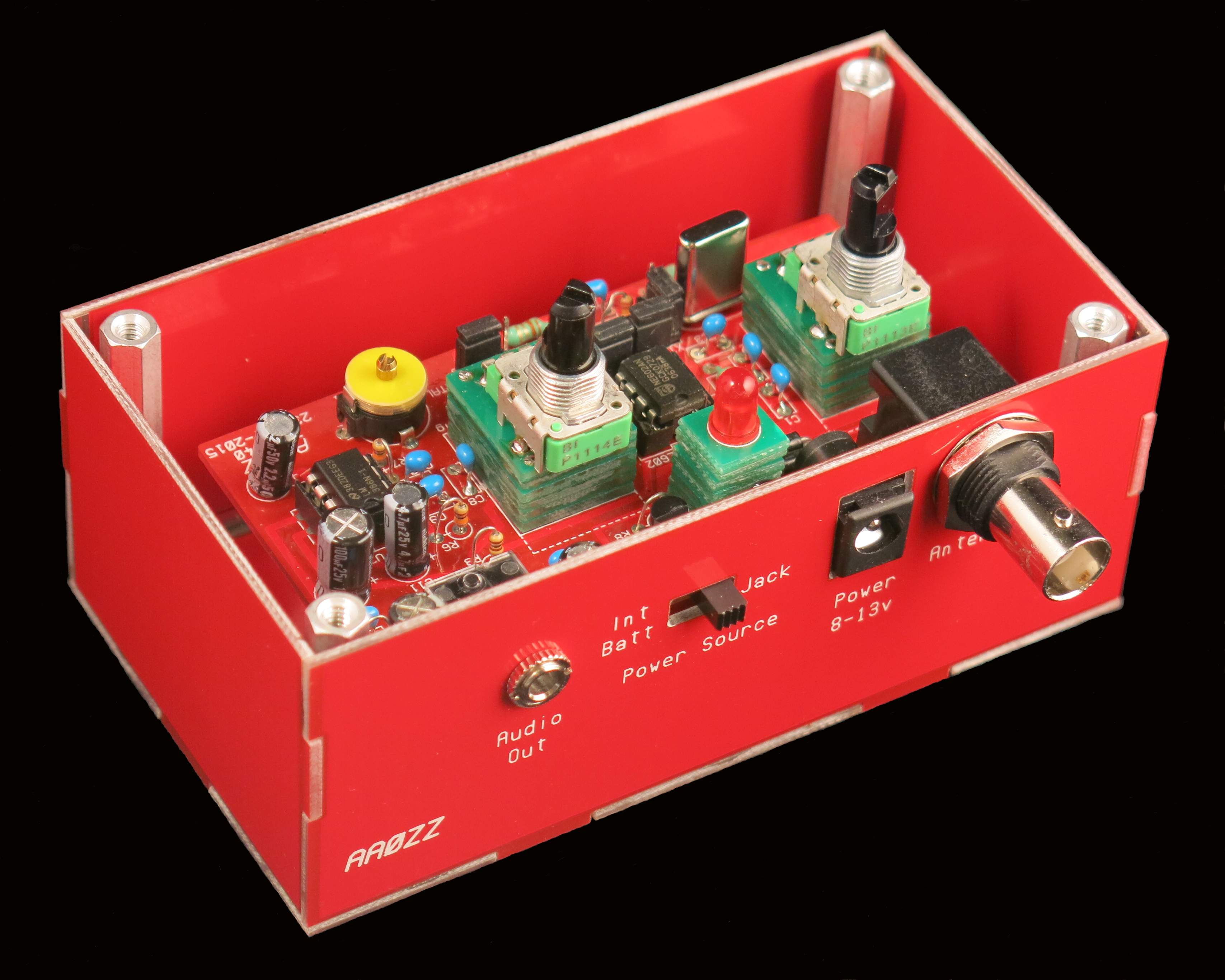
ZZRX-40 PCB in Case
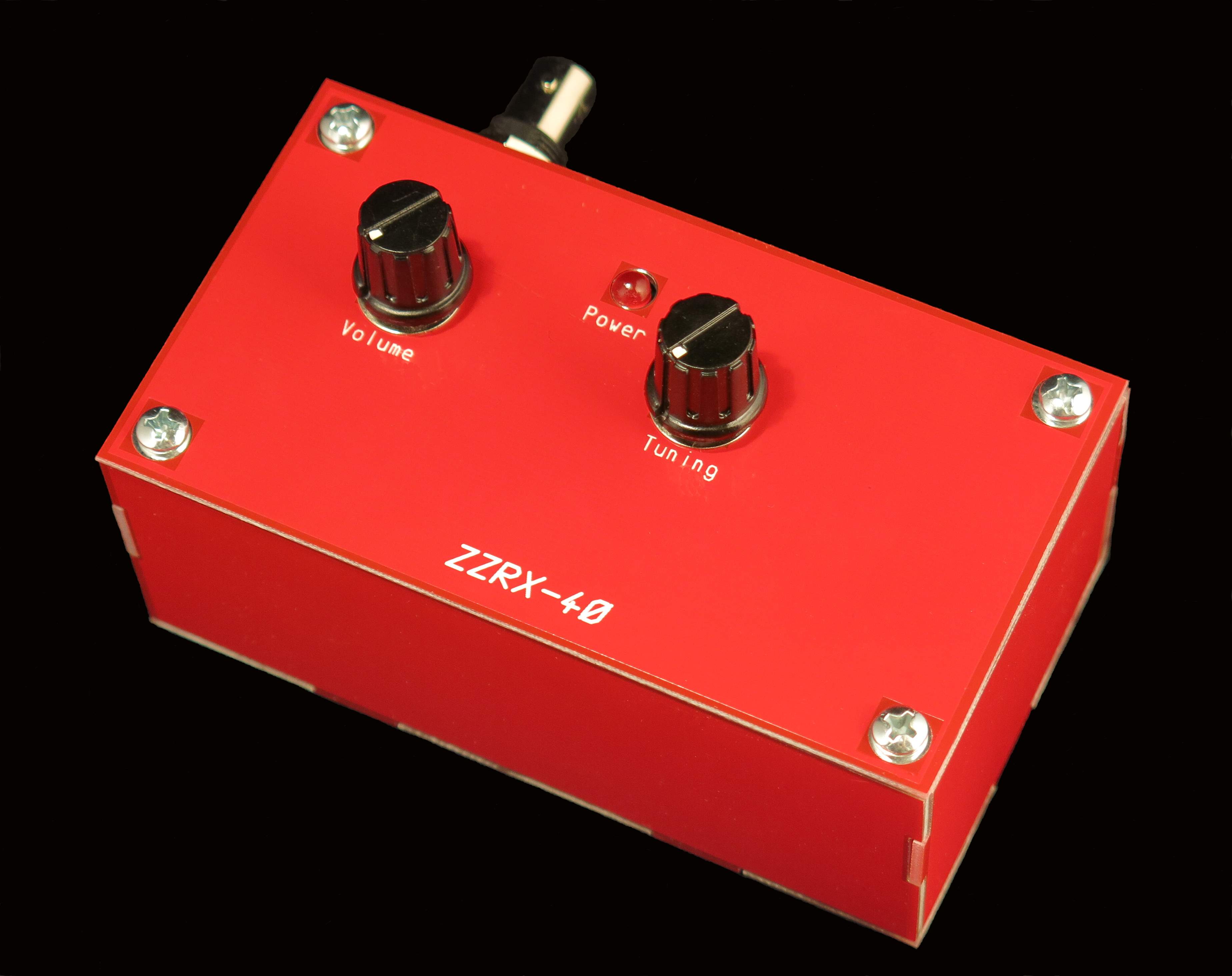
ZZRX-40 Complete
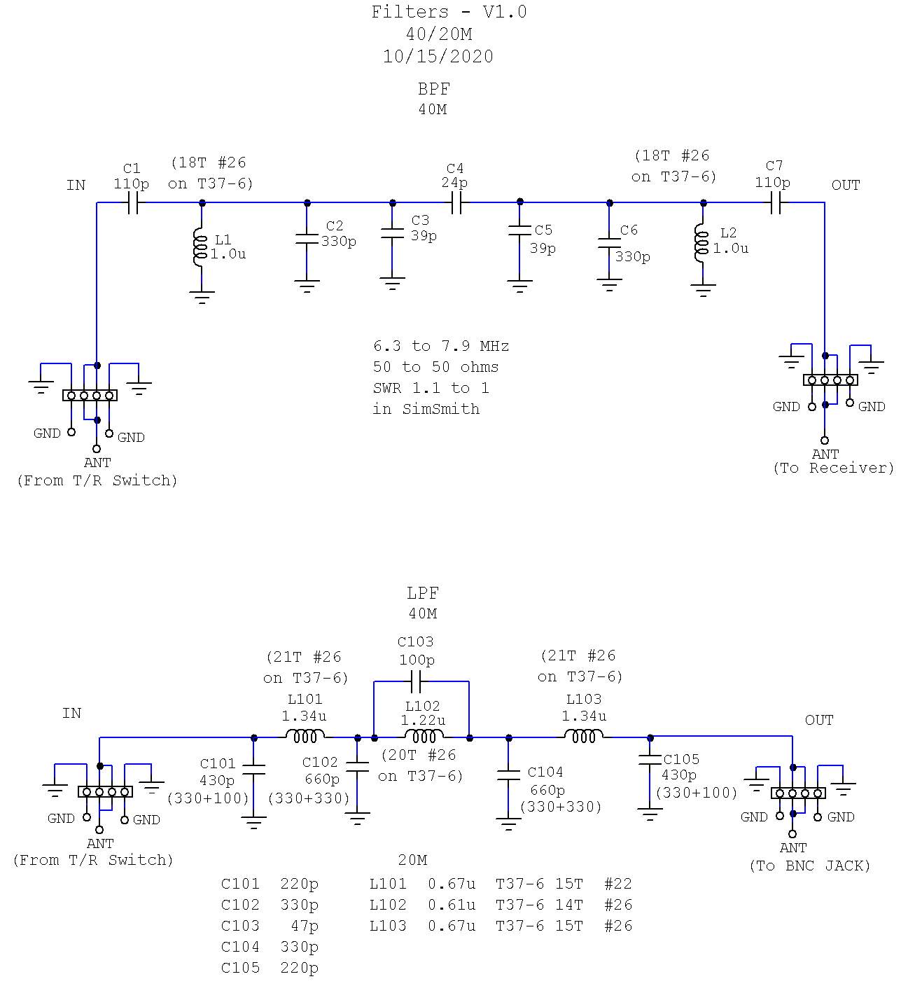
Schematic - ZZRX-40 Receiver (JPG format)
Theory Of Operation - Direct Conversion Receivers Including ZZRX-40 (PowerPoint .PPTX format)
|
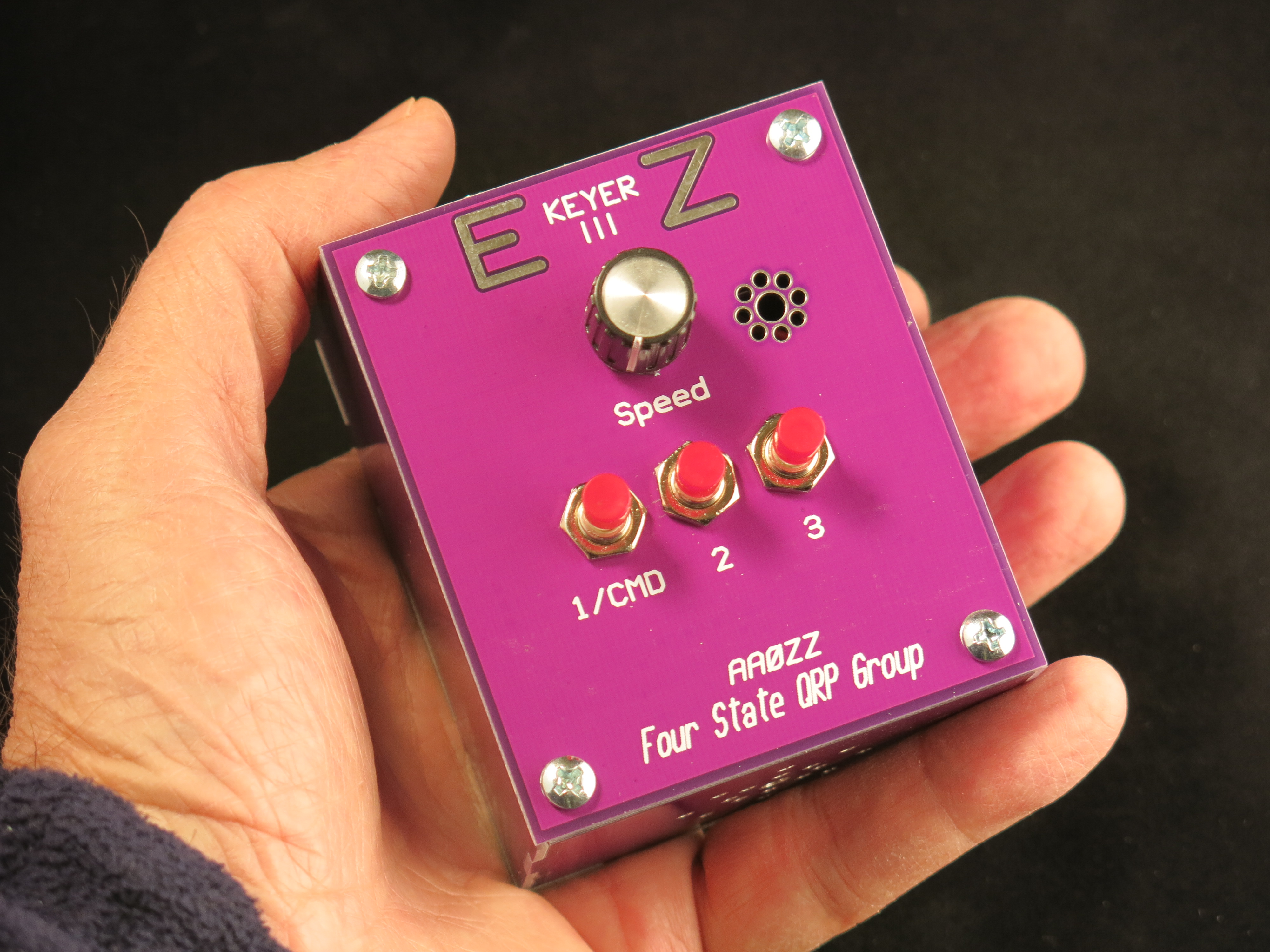
The AAØZZ EZKeyer III
|

|
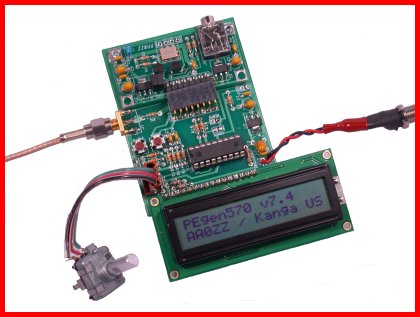
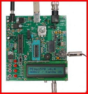
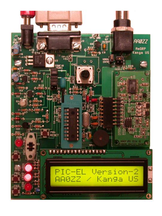
The PIC-EL III
Now with a USB Interface!
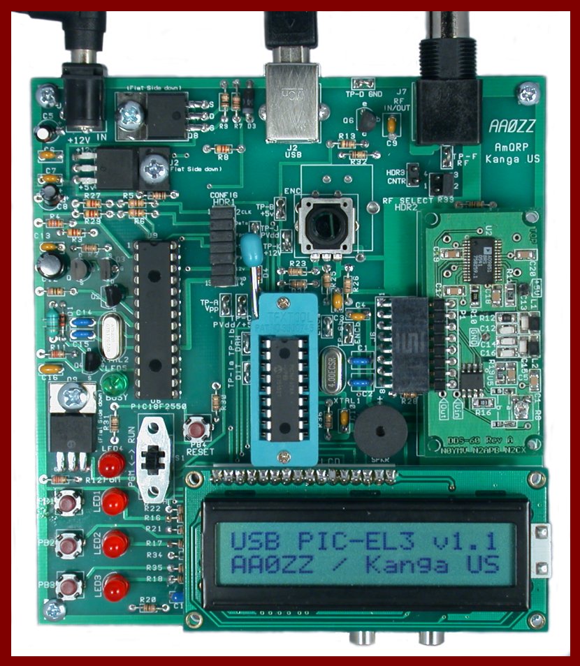
Support
|
|
Elmer 160 Lessons by John McDonough, WB8RCR
Microchip PICKit2 Application (for PIC-EL III)
Use with Elmer 160 Lessons |
|
|
|
|

Older Ham Radio Projects
|
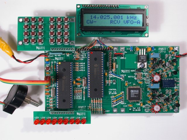
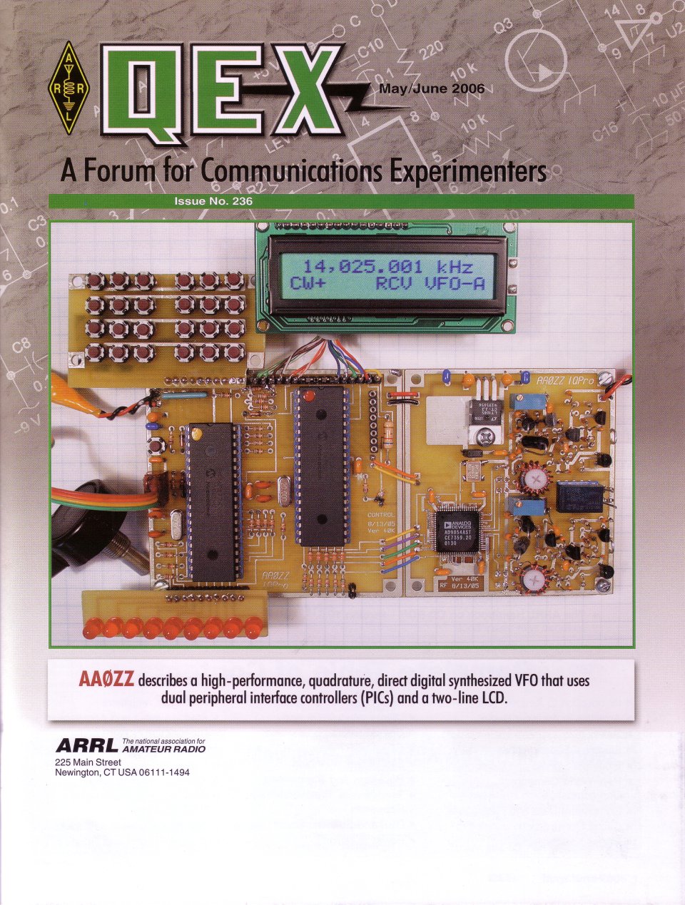
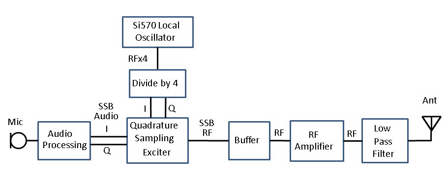
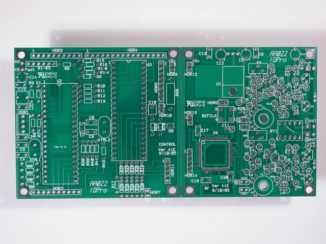
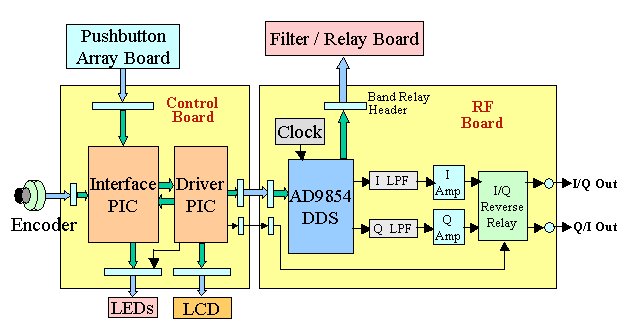
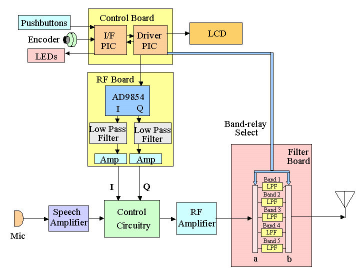
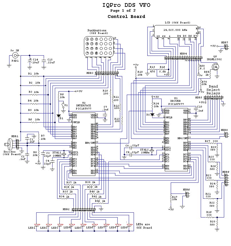
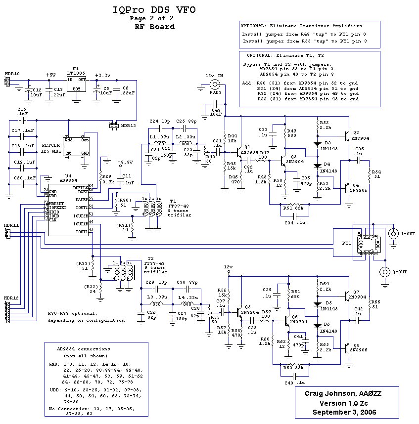
IQPRO
(Click to enlarge) |
||
|
|||
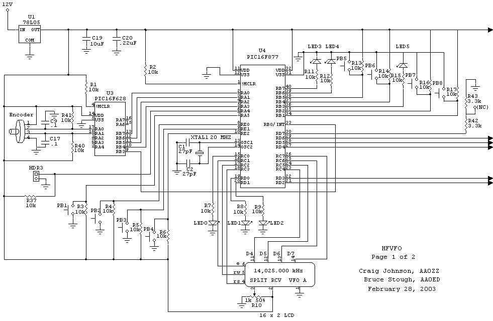
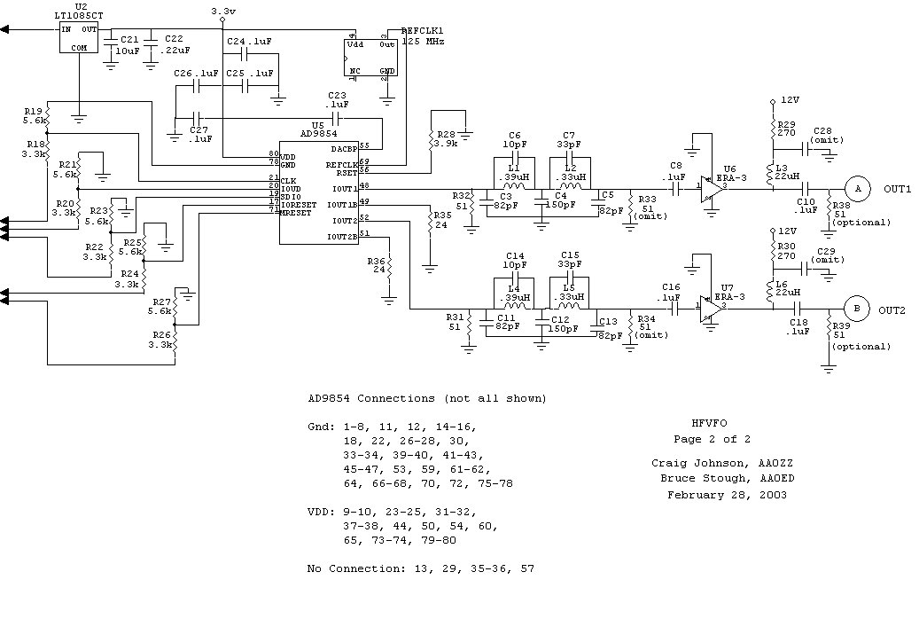
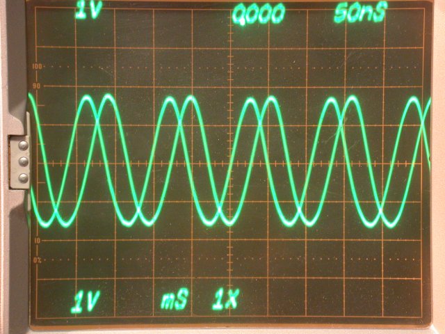
See my YAHOO Group: DDS-VFO for Support / Discussion / Files / Pictures / Documentation Complete Manual: Manual Ver 1.0f (in PDF format) Updated 01/31/05 Schematic: Page 1 of 2 (drawn with CircuitMaker) PIC16F877 Symbolics v5.19b HEX (Main Control) PIC16F628 Symbolics v1.1c HEX (Encoder) Parts List (updated 11/13/2004 - with prices) Perfect quadrature output! (0 - 30 MHz) Performance Analysis (PDF) New 01/31/05 Don Huff, W6JL, uses a HFVFO prototype with R2Pro PowerPoint slides from my FDIM Presentation on May 15, 2003
Sorry, but the IQ-VFO kits are sold out and no longer available from AmQRP.
|
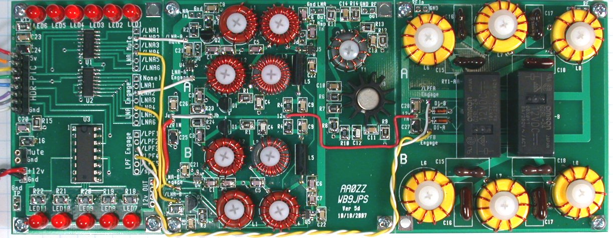
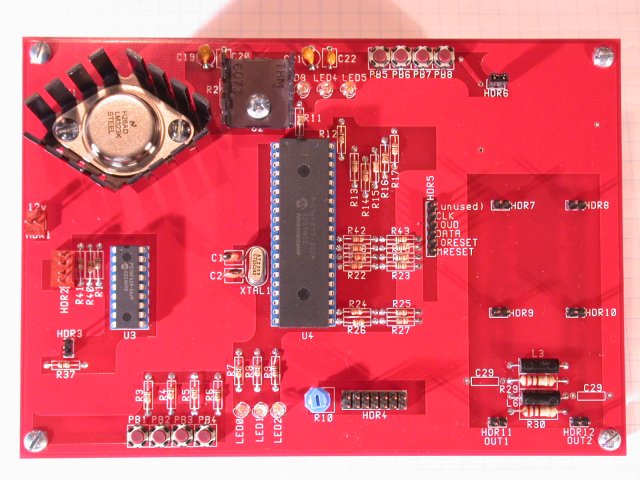
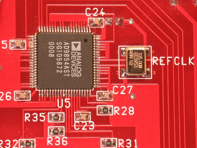
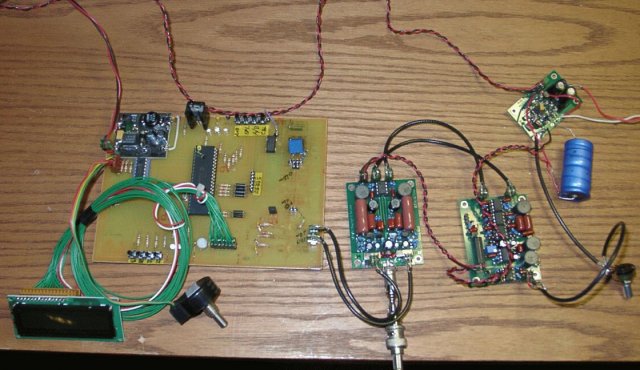
HFVFO board - top
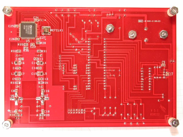
HFVFO board - bottom
HFVFO board - AD9854
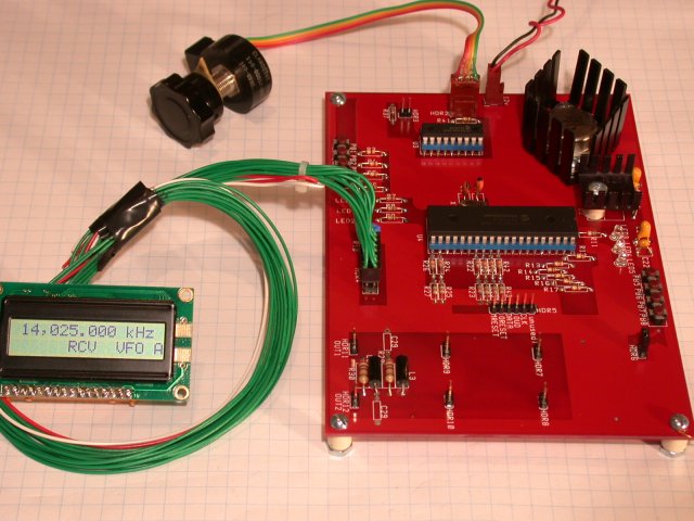
HFVFO board - running
|
||
|
PIC-EL II
(Click to enlarge) |
||
See See: ELMER 160 Home Page My contribution to the project -- to design the Programmer/Project board. (I called it the PIC-EL Board.) Here's how it works! PIC-EL Design Description Pictures: - My first conceptual schematic - My first prototype (Manhattan style) - Getting the first bugs out. At least the programmer works. - My second prototype - Now it's a signal generator (with my SIGGEN3+ code driving a DDS Daughtercard) - 2-layer circuit board - The circuit board (created with WinBoard) - Final Prototype - The final prototype APPLICATION CODE FOR THE PIC-EL - PICELgen v1.4 source code- Signal Generator using PIC-EL and DDS-30 DDS Daughtercard - PICELgen v5.2 source code- Signal Generator using PIC-EL and DDS-30/DDS-60 DDS Daughtercard - K8-PE-Ver2-Keyer source code- K8 Keyer (16F84) for PIC-EL (Original by Steven Elliott, K1EL) - K8-PE-Ver2-Keyer documentation- Documentation for K8 Keyer (16F84) for PIC-EL - K8-PE-Ver4-Keyer source code- K8 Keyer (16F628) for PIC-EL (Original by Steven Elliott, K1EL) - K8-PE-Ver4-Keyer documentation- Documentation for K8 Keyer (16F628) for PIC-EL PIC-EL (Rev A) Modifications - PIC-EL 16F628 Mods - PIC-EL (Rev A) modifications required to use a 16F628 PIC My presentation at ATLANTICON 2004 (March 27, 2004) - The PIC-EL and Beyond - My paper for the Atlanticon Proceedings - PowerPoint Slides - My presentation The PIC-EL Version 1 kits were only available from AmQRP for a short time.
(Approximately 800 were sold.)
| PIC-EL Schematic
PIC-EL Production 1
|
||
|
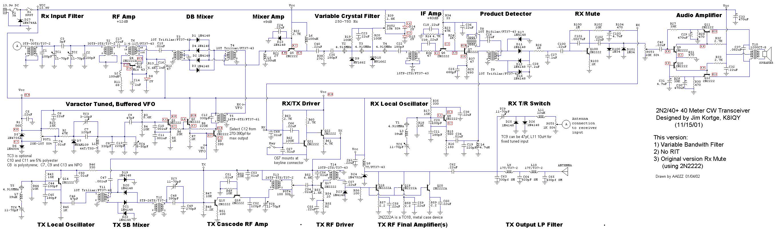
Design details at Jim Kortge's home page: K8IQY's 2N2 Homepage Schematic (drawn with CircuitMaker) My 2N2-40 Layout (PowerPoint format - to download and print - actual size) |
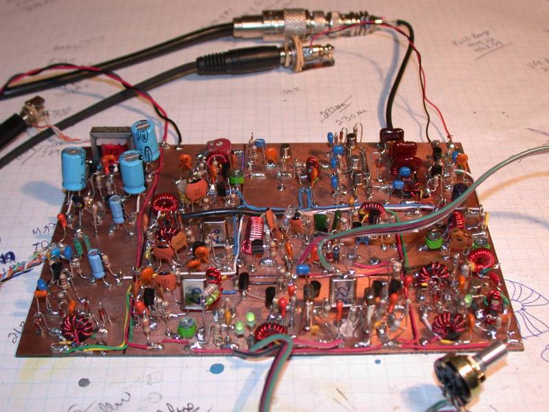
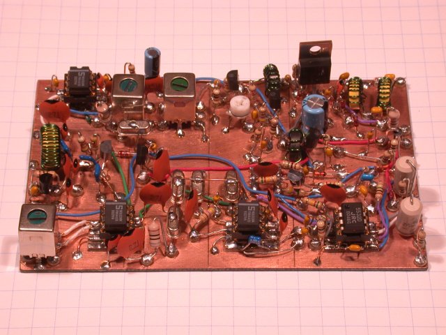
My 2n2-40 transceiver (Click to enlarge) Yes, it works! | ||
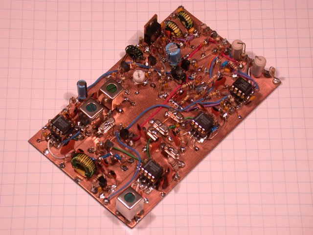
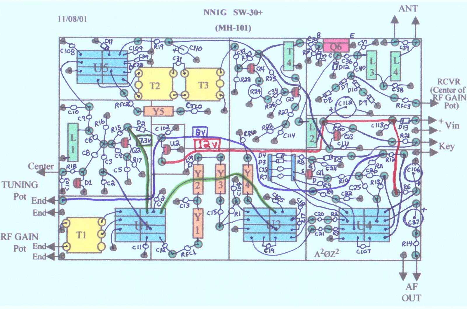
My MH101 ("manhattan" style) version of the SW 30+ Picture 1 Picture 2 - Pad layout in PowerPoint format (actual size): MH101 Pad Layout - All parts layout: All Parts
|
My MH101 transceiver (Click to enlarge) Yes, it works too! |
 PIC Programmer for 18-pin PICs via PC Serial Port


-18.BMP)
-18.BMP)
Biographical sketch (updated 5/2022): AAØZZ Bio
Send me E-Mail at:
Go to my "main" home page at
www.cbjohn.com/cbj
Last Updated 10-May-2022
Hit count since 6/2021
This web page was created entirely with a text editor!
![]()
(Sorry I had to show the Email address like this. I'm sure you know why.)
- Craig, AAØZZ
Why? It's just because of my curiosity about how HTML works!